Introduction
This topic deals with the Life-cycle Model of a Plant:

which translates to the following model:
Placeholder Model
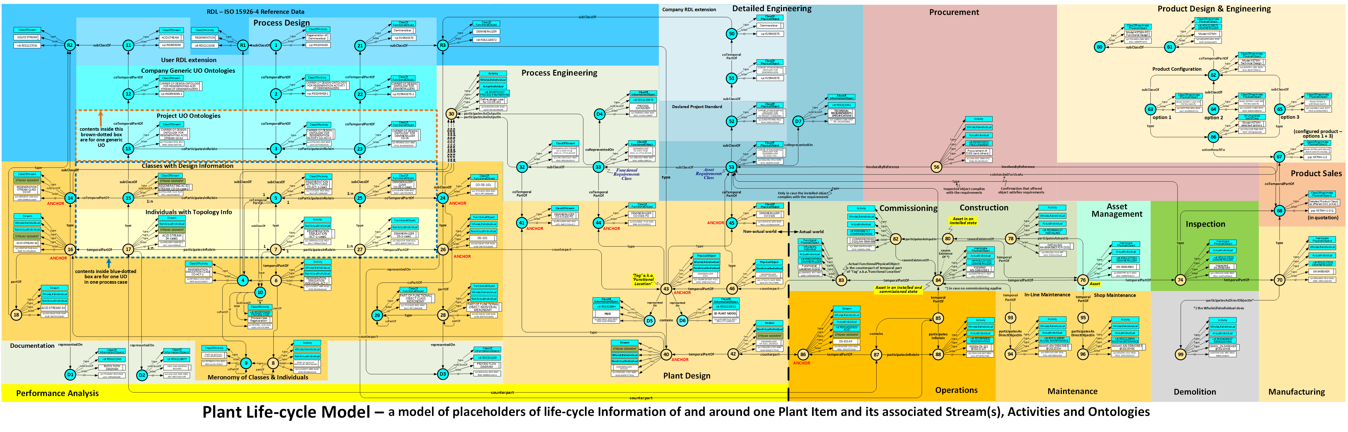
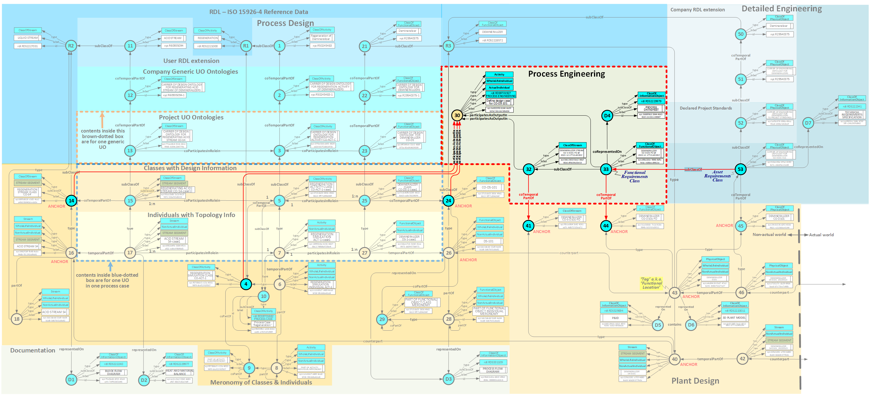
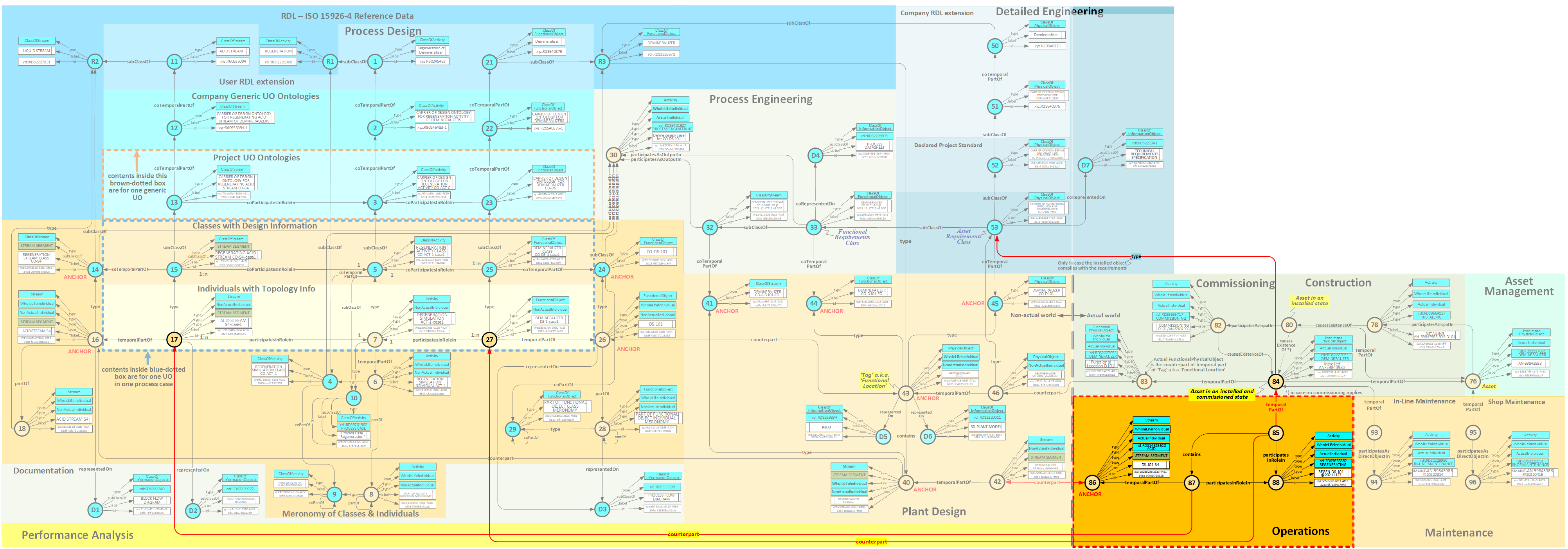
The Plant Life-cycle Model shown below is clearly a "back bone" model for the integration of life-cycle plant information. It shows the life cycle of ONE plant item in the structure of the Plant Life-cycle Information Model.
Each of the numbered nodes plays a role in one to many Template instances, other than the templates that replace the shown predicates (see Predicates used).
NOTE - Interrelationsships between Nodes of different instances of this Lifecycle Model shall be such, that the interrelated objects are in the same Lifecycle Activity. See for example here
Predefined Code
In each of the above chapters you will find the applicable predefined Turtle code in a generic form, that can be used to declare the information placeholders and their shown interrelationships. These have been collected in one file that you can find here
What are you looking at?
You are looking at a plant item from its birth (Process Design) to its grave (Demolition), where for each stage it is life a separate Node has been reserved, because each such node has its own information.
In fact there are TWO items:
- a PossibleIndividual in a Design World, with two sub-Worlds:
- a NonActual FunctionalObject that shall be able to handle the Stream(s) in Process Design, residing in a Process Design World ;
- a NonActual PhysicalObject ("Tag") in Plant Design, that is a counterpart that FunctionalObject, residing in an Engineering World;
- an Actual PhysicalObject in the real world, that implements that Tag. In the life of a Tag more than one actual items may successively implement that Tag, e.g. as a result of replacing a defective pump.
- rdf:id - required for graph, but implied in Turtle;
- rdf:type - if fixed: use as-is, in case it can change: tpl:ClassificationOfIndividual;
- rdfs:label - use as-is in declarations;
- rdfs:subClassOf - if fixed: use as-is, in case it can change: tpl:SpecializationOfClassOfIndividual;
- tpl:causesBeginOf - use tpl:ActivityCausesBegunIndividual;
- tpl:coIntendedForUseAs - tpl:ClassOfIntendedRoleAndDomainDefinition;
- tpl:coPartOf - use tpl:ClassOfCompositionDefinition;
- tpl:coParticipatesInRoleIn - use tpl:ClassOfParticipationDefinition;
- tpl:coRepresentedOn - use tpl:ReferenceToClassOfIndividualOnDocument;
- tpl:coTemporalPartOf - use tpl:ClassOfTemporalWholePartDefinition;
- tpl:contains - use tpl:ContainmentOfAnIndividual;
- tpl:implements - use tpl:InstallingPhysicalObjectInFunctionalLocation;
- tpl:unionResultTo - use tpl:UnionOfEnumeratedSetOfClass;
- tpl:involvedByReferenceIn - use tpl:InvolvementByReferenceOfClassInActivity;
- tpl:partOf - use tpl:CompositionOfAnIndividual;
- tpl:participatesAsDirectObjectIn - use tpl:ParticipationOfPhysicalObjectInActivity;
- tpl:participatesAsInputIn - use tpl:InvolvementByReferenceOfClassInActivity;
- tpl:participatesAsOutputIn - use tpl:InvolvementByReferenceOfClassInActivity;
- tpl:participatesInRoleIn - use tpl:ParticipationOfPhysicalObjectInActivity;
- tpl:representedOn - use tpl:ReferenceToIndividualOnDocument;
- tpl:temporalPartOf - use tpl:IndividualHasTemporalPart;
- Process Design
- Process Engineering
- Plant Design
- Detailed Engineering
- Product Configuration
- Product Sales & Procurement
- Manufacturing & Inspection
- Asset Management
- Construction & Commissioning
- Operations
- Maintenance
- Performance Analysis
- Demolition
- ClassOfActivity [4] and its class of temporal part Class(es),
- ClassOfStream [14] and its class of temporal part Class(es),
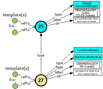
- ClassOfFunctionalObject [24] and its class of temporal part Class(es),
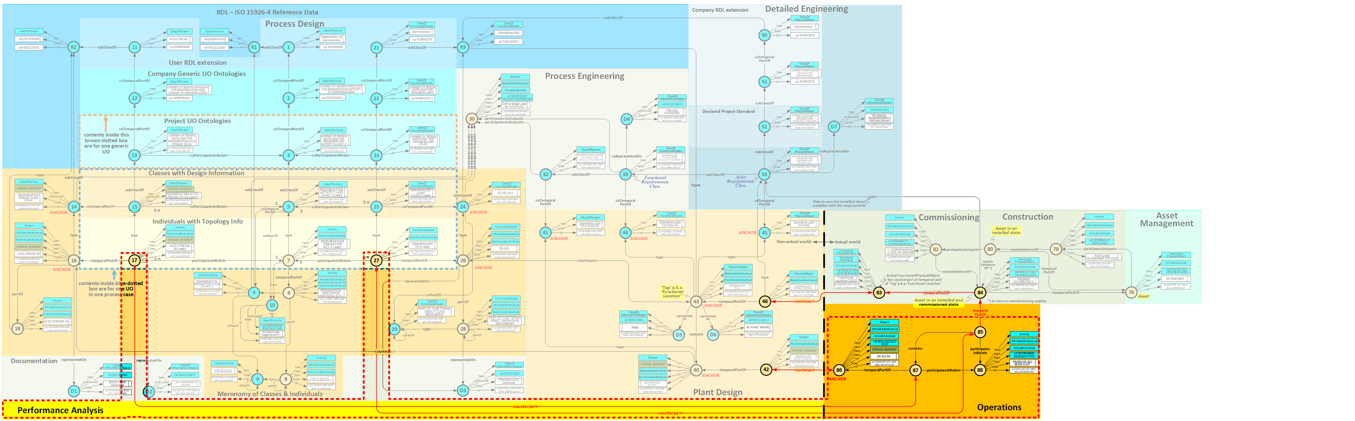
- When the Tag is being declared it is typed with what we call its 'Essential Type', that is the class it is a member of for its entire existence ; so 'DEMINERALIZER' rather than 'MIXED BED DEMINERALIZER' since the latter may change ;
- When the Tag is being declared we may link it to FunctionalObject [26] by means of a 'counterpart' relation ; thus from the Tag we have access the Process Design history of [26]
- When the Tag is being declared we automatically declare a companion ClassOfFunctionalObject [44] and a companion ClassOfPhysicalObject [45] via a hard-coded rdf:type instead of a Classification template. All three are "anchors" that remain empty of information and remain in existence as long as the Tag is functionally required in the plant and/or its life-cycle information needs to be kept in store ;
- A temporal part of the Tag is represented on a P&ID [D5], and another temporal part of the Tag is represented in a 3D Model [D6] ;
- An explicit temporal part [46] of the Tag, existing in the Design World, is linked with the applicable Actual FunctionalPhysicalObject [83], existing in the Real World, via a 'counterpart' relation. This has a history that can be found here
- A Tag contains, in many cases, a Stream [40], that is, at declaration time, hard-typed with an anchor ClassOfStream [41]. The latter is an anchor for the Stream part [32] of the Functional Requirements Class [33].
- Like the Tag, the Stream [40] is a counterpart of the Stream anchor [16] in Process Design, thus giving access to the design information.
- Finally an explicit temporal part [42] of the Stream, existing in the Design World, is linked with the actual anchor Stream [86], existing in the Real World, via a 'counterpart' relationship.
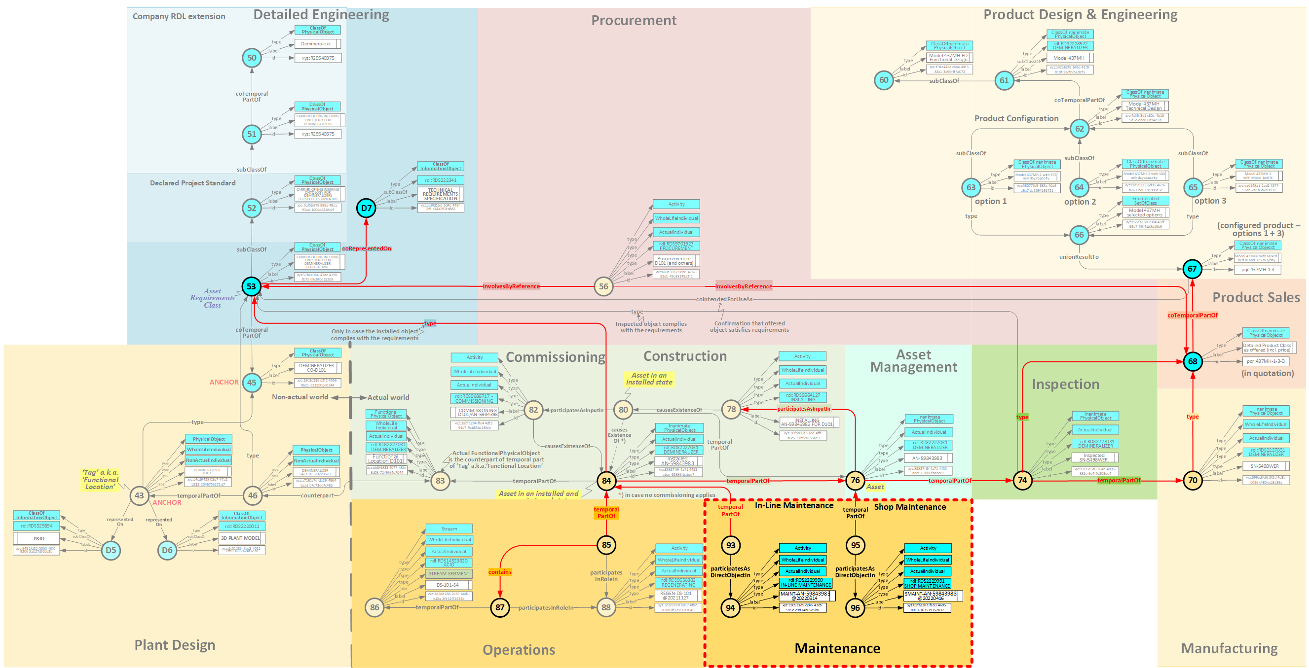
NOTE - The Process Design world, with its (possible) multiple process cases, is here considered to be a separate Possible World - Starting with the process data, that are inherited from [33], the specification [D7] for the Asset Requirements Class [53] is being written. This includes physical requirements, such as material of construction and explosionproofing;
- The Asset Requirements Class [53] is a class of temporal part of the "anchor" ClassOfPhysicalObject [45] that types the Tag [43];
- The Asset Requirements Class [53] is 'involved by reference' in a Procurement Activity [56] , together with the 'Detailed product class, as offered (incl. price)' [68]
- The PhysicalObject [74] that is being inspected can be classified with the Asset Requirements Class [53] in case it fulfills the requirements set forth in the latter ;
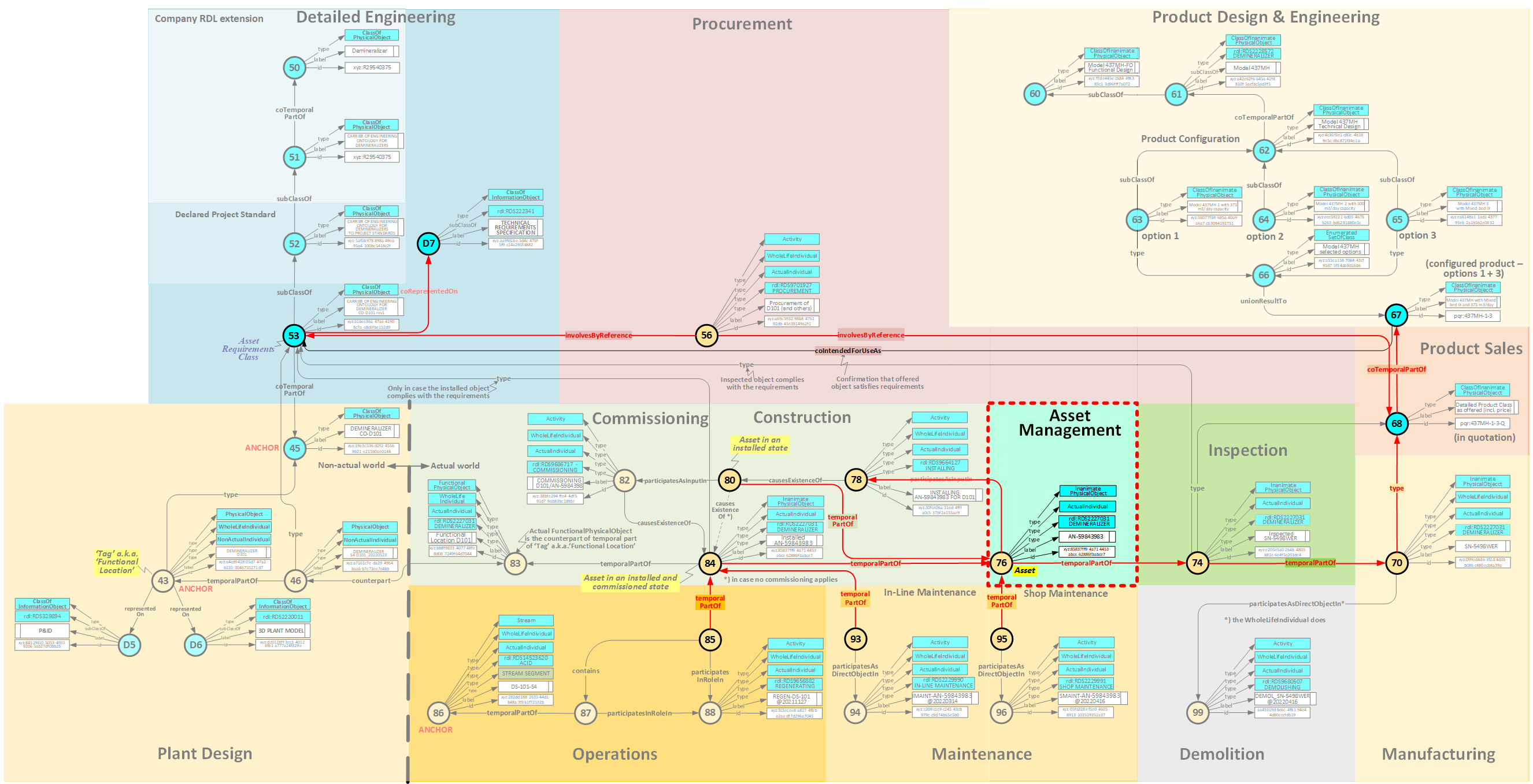
- If the installed PhysicalObject [84] is compliant with the requirements of the Asset Requirements Class [53] it can be classified with the latter.
NOTE - The counterpart relationship with the Tag only states that PhysicalObject [84] is a real-world counterpart of the temporal part of the design-world Tag [46] and not that it complies with the Tag requirements. That can be confirmed by classifying/typing the installed item with the applicable Requirements Class [53]. /li> - As said, the Installed Asset [84] is a temporal part of Asset [76];
- The Installed Asset [84] is a temporal part of Actual FunctionalPhysicalObject [83], that is the placeholder of "as-built" information of that Tag;
- The Actual FunctionalPhysicalObject [83] in the Real World has is the counterpart of temporal part[46] of Tag [43] in the Design World; this allows for access to all Tag-related Design & Engineering information. See also here ;
- In case the Installed Asset [84] is compliant with the Asset Requirement Class [53] then it is classified with same ;
- The Installed Asset [84] can, via its temporal part [85], participate in an Operations Activity [88], e.g. pumping boiler feedwater to E-101;
- The Installed Asset [84] can, via its temporal part [93], participate in an In-line Maintenance Operation [94]
(for a Shop Maintenance it needs to be uninstalled, and then becoming another temporal part [95] of Asset [76] again) and participating in an Shop Maintenance Operation [96]) - In-line Maintenance - where the maintained object remains installed : a temporal part [93] of the Installed Asset [84] participates in In-line Maintenance Activity [94];
- Shop Maintenance - where the maintained object is uninstalled and transported to the maintenance shop : a temporal part [95] of Asset [76] participates in Shop Maintenance Activity [96];
- It can be seen that, starting at Maintenance, both the Design & Engineering information, as well as the Manufacturer information can be reached.
- Stream [87], in a process case, is a counterpart of the Process Design ClassOfStream [17], in the same process case, giving access to design data for comparison (iff access rights allow).
- Installed Asset [85], in a process case, is a counterpart of the Process Design ClassOfFunctionalObject [27] in the same process case, giving access to design data for comparison as well (iff access rights allow).
In broad strokes this model is set up as follows:
Interrelationships between lifecycle stages of one plant item
The nodes in the life of the plant item are interconnected in an ISO 15926-compliant manner. They form a "local road system" between those nodes. Note that the relations temporalPartOf and coTemporalPartOf (co = classOf) are there to allow for temporally different parts of the whole item. For example, Node 53 (Asset Requirements Class) is a coTemporalPartOf Node 45, where the latter is the "ANCHOR", i.e. the top of a temporal hierarchy that itself has no information and remains in the records as long as that is of interest for the user. Node 53 starts with, for example, the label "CO-P101-rev0", and "CO-P101-rev1" is the next instance of Node 53, so the next coTemporalPartOf Node 45. "CO-P101-rev0" remains on record forever. In this way a full audit trail is formed, but also this information remains available for analysis, for example when a revamp is required.
Interrelationships between plant items
There is also an "interlocal road system" between nodes in the life cycles of different plant items. Those are covered by instances of templates like ClassifiedDirectConnectionOfTwoIndividuals. A strict rule is that both plant items shall be in the same Lifecycle Activity, so you can't connect a designed pump (Node 43) to an actual pipe (Node 84). The available Functional Diagrams, viz P&IDs, Loop Diagrams, One-line Diagrams, etc, are essential for the topological information of this "interlocal road system".Information about plant items
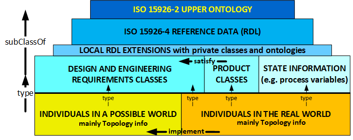
Generally topological information is attributed to Individuals, both in the design world and in the real world (Node 43, Node 84).
Design and Engineering information is attributed to Classes (Node 53, Node 68).
Finally state information is attributed to real-world Individuals (Node 70 and up) and, equally important, to real-world Streams (Node 86 - 87).
In due time a list of typical information types will be published for each Node.
What does this mean in practice?
Well, it is certainly not required to instantiate the entire model anytime you want to declare a new plant item. The model tells you HOW to declare it by relating it to other nodes that have already been declared. So, in case you declare "CO-P101-rev1" you add the template IndividualHasTemporalPart, thereby linking it to Node 45. In the excerpt models for the various lifecycle activities (below) relations to other lifecycle stages are shown in red, and can be used for that purpose (iff the other side is already known, of course). In case more relations are known, use them all.
Placeholders?
A Placeholder is a Thing that is referred to from the signature of one or more template instances. That Thing then plays a Role in the semantics of that/those template(s).
Predicates used
The following predicates (rdf:Property) are being used in above graph:
Dedicated graphs, one for each Lifecycle Activity, can be found here:
NOTE - The descriptions of the various life-cycle activities have a focus on the model, i.e. how information placeholders are interrelated. Not on the held information itself.
As a consequence these descriptions may not do justice to the scope of the disciplines.
Process Design
This first part of the lifecycle has the following model:
Exegesis
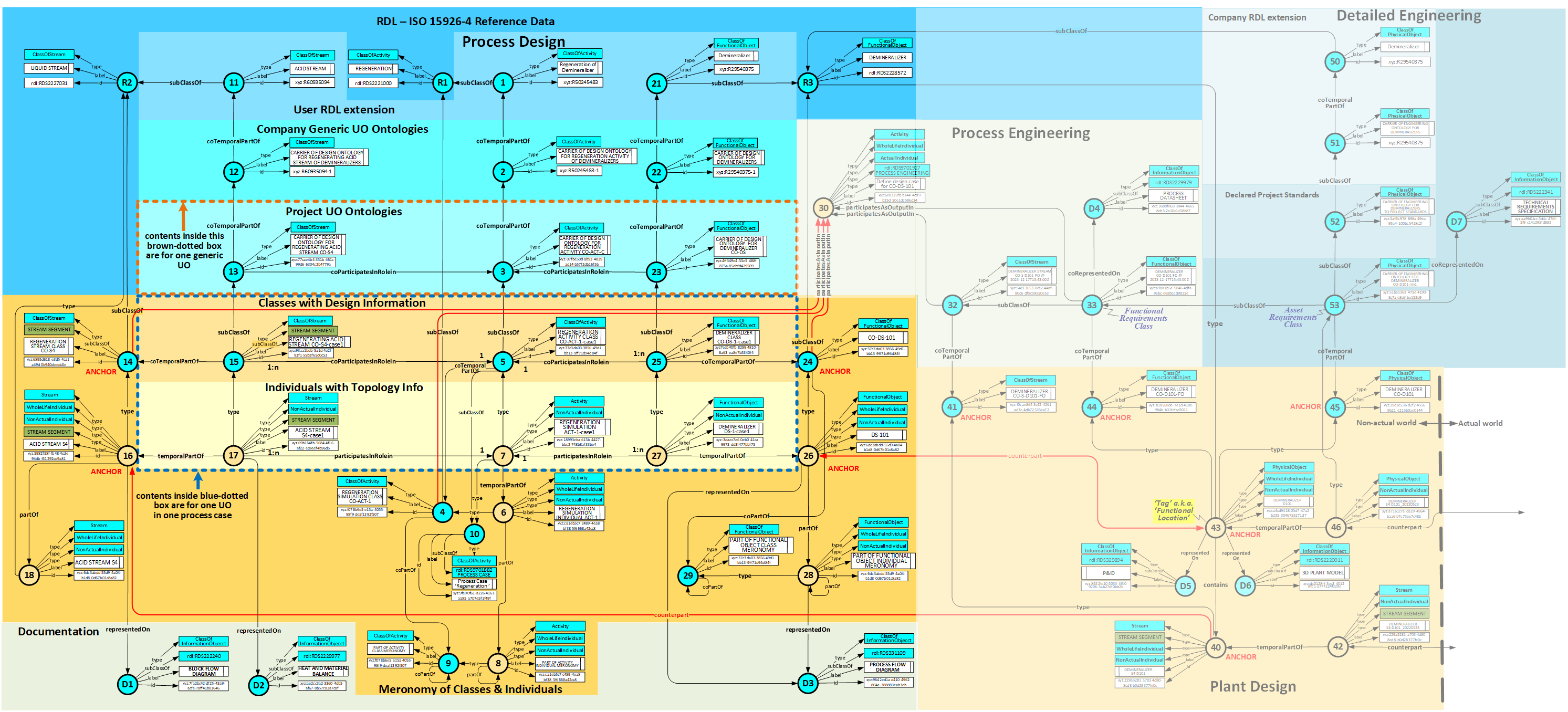
Plant Design and Process Engineering are included in the above diagram because they are impacted by Process Design information.
Process Design deals with hydraulic and energy networks, with Activities [7] and Streams of Matter and Energy [17] above). Next comes the FunctionalObject [27] that can, functionally, perform these Activities.
We start with an 'Anchor' (WholeLife) Stream 16] that is on a Block Flow Diagram [D1], and a temporal part thereof [17] of which the values are represented on a Heat & Material Balance [D2] (see below).
And we have a Anchor FunctionalObject [26] that is represented on a Process Flow Diagram [D3].
That Anchor Stream [16] is a member of Anchor ClassOfStream [14] that is a specialization of a ClassOfStream [R2] in the RDL.
That Anchor FunctionalObject [26] is a member of Anchor ClassOfFunctionalObject [24] that is a specialization of ClassOfFunctionalObject [R3] in the RDL.
Between that Anchor ClassOfStream [14] and Anchor ClassOfFunctionalObject [24] we see a ClassOfActivity model of which the Activity model between Stream [17] and FunctionalObject [27] is a member/instance.
In the top of the diagram is a set of reference data that can be defined in an RDL extension, for example the CFIHOS RDL extension, or company-specific extensions thereof (OR a comapny-specific extension directly of the RDL for any company outside the influence sphere of CFIHOS).
The classes [12], [2] and [22] have an information set, in the form of a set of generic templates, around them, defining which information must be given for the stream, the activity and the functional object that they share.
Note that there can be more than one stream and/or more than one functional object related to an Activity.
These templates are semi-specialized, for example they state that the stream must have an UPPER LIMIT OPERATING TEMPERATURE, with or without mentioning that this must be in DEGREE CELSIUS, but they do not define a numeric value. Optionally further details can be defined for a project in a class of temporal part [13], [3] and [23].
Ultimately that value, and eventually also the Units of Measure, is attributed to a Requirements Classes [15], [5] and [25].
Model for Process Cases
In the above diagram you see an area within brown-dotted lines. That is basically representing an ontology for a process case. It follows the generic ontology of the area above it ([12], [2] and [22]). The coTemporalPart relations allow for zero-to-many such temporal parts for variations of process cases.
NOTE - The relations temporalPartOf and coTemporalPartOf actually are specializations that are relevant for a period in time between a given EffectiveDate and a DeprecationDate . Temporal parts may exist simultaneously over different periods in time.
In the above diagram you also see an area within blue-dotted lines. That is basically representing one process case with its Requirements Classes. Those requirements follow the ontology just discussed. A process case is kind of 'suspended', like a trampoline, by 'Anchor' individuals and classes by means of temporalPartOf and coTemporalPartOf relations. Again, keep in mind that process cases usually have more than one (ClassOf)Stream.
The Individuals [17], [7] and [27] are, predominantly, the placeholder for topological information (source, destination, location), and the Classes [15], [5] and [25] are the (functional) Requirements Classes, holding the design information for a process case.
The applicable process case is defined by typing the Activity [7] with ClassOfActivyty [10], and making ClassOfActivity [5] a subclass thereof. Note that a process case can dictate more than one Activity in the plant, such as opening or closing valves, starting or stopping motors, setting setpoints of controllers, etc. All affected Activities are then a member of the ClassOfActivity [10].
Interfaces with Plant Design and Process Engineering
The Anchor FunctionalObject [26] has the Anchor Tag [43] as its counterpart. That means that the Process Design history is accessible for that Anchor Tag. Keep in mind that that Anchor FunctionalObject is typed with its Anchor ClassOfFunctionalObject [24] and via the coTemporalPartOF relation with [25] (which may involve a number of simulations for a number of modes of operation).
The Anchors [4], [14] and [24] are used by Process Engineering [30] for defining the "design case" [33] that is input for Detailed Engineering. Also here keep in mind that there may be more than one set of simulation data of more than one mode op operation, that are used by the Process Engineer to define that "design case".
Block Flow Diagram
The BFD (Block Flow Diagram [D1], source: The Engineering Toolbox and OSHA) shown below gives an example:

Participating in Unit Operations (= ClassOfActivity) are Stream classes (e.g.WasteWater). This can be modeled by using the template ClassOfParticipationDefinition that is used in the starting diagram.
So in above BFD the tag P14 at Node 6 it can be seen that stream S11 participates in the role of 'input' and stream S12 in the role of 'output' (so in this case two instances of that template).
Heat and Material Balance
An important end product of Process Design is a document (or file) called Heat & Material Balance [D2], giving all details about the streams:

Process Flow Diagrams
The next step is to find FunctionalObjects that can perform the Activities in the BFD. This results in the Process Flow Diagram (PFD) [D3], such as this example:

Skeleton Process Flow Diagram (PFD) for the Production of Benzene via the Hydrodealkylation of Toluene (source: informIT)
Code listing for this life-cycle activity
Don't let it scare you off, this one is the most complex; Click here
Process Engineering
The input for Process Engineering are the results of Process Design. Together with the other disciplines de P&ID (Piping and Instrumentation Diagram) is set up.
In the context of this model it is important to note that Process Engineering defines the Process Conditions and the Stream characteristics which have to be taken into account by Detailed Engineering. This information is represented in a Process Datasheet [D4] that defines the Functional Requirements Class [33]. A typical example of the data involved is this part of the API 610 datasheet :

Compared with the Process Design data these conditions may include adaptations caused by engineering rules, such as a required overcapacity, safety margins, etc.
Interfaces with Process Design, Plant Design and Detailed Engineering
The Activity [30], typed with rdl:RDS9701927 (PROCESS ENGINEERING), has the information, attributed to:
The information set of ClassOfStream [32] is inherited by the Functional Requirements Class [33].
The Functional Requirements Class [33] is a (class of) temporal part of ClassOfFunctionalObject [44]; the semantics of that are explained below in chapter Plant Design'. It boils down to the following: The ClassOfFunctionalObject [44] is declared to be an 'anchor', i.e. it remains fixed in place as long as the information about its member Functional Location [43] is kept in store. The Functional Requirements Class [33] may change over the life cycle of the plant into revisions rev0, rev1, etc. This structure with a coTemporalPartOf (dm:ClassOfTemporalWholePart) relationship allows for a cradle-to-grave audit trail of the functional requirements of the Functional Location a.k.a. 'Tag'.
In a similar way the design case for the Stream class [32] is a coTemporalPartOf anchor Stream class [41].
The Functional Requirements Class [33] is a superclass of the ClassOfPhysicalObject [53] because that 'Asset Requirements Class' adds the technical requirements to the functional requirements of [33].
Code listing for this life-cycle activity
Click here
Plant Design
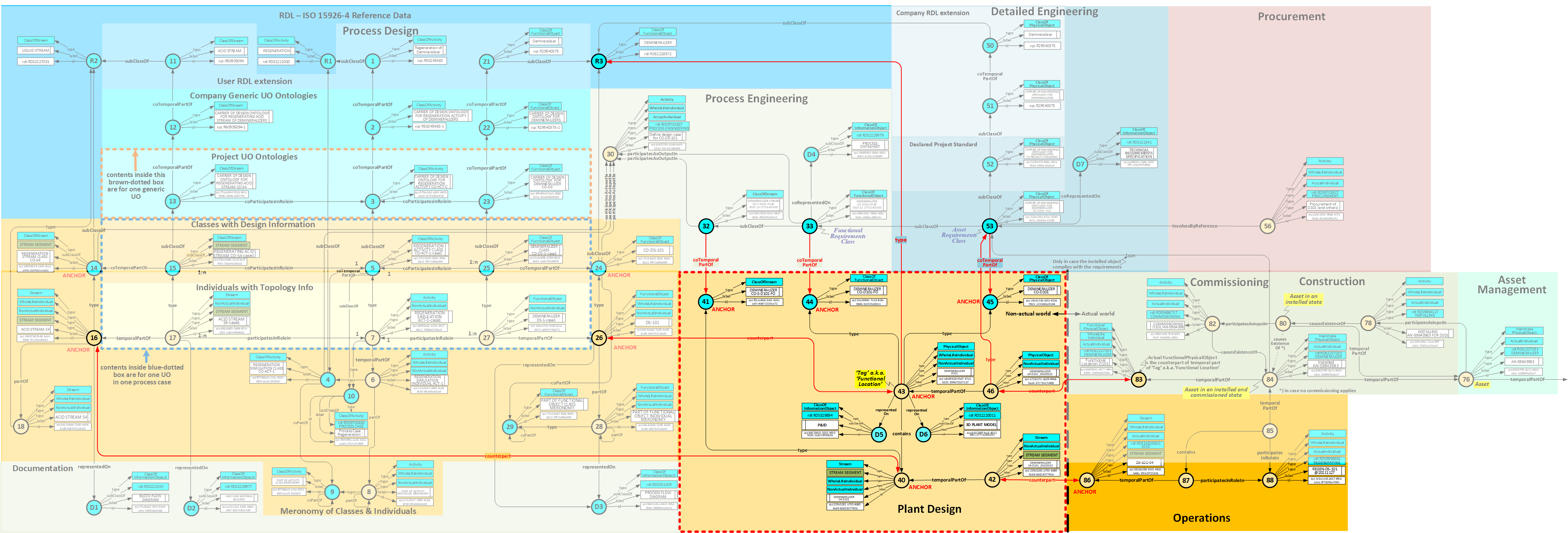
Schematic diagrams are being produced, like the P&IDs (Piping and InstrumentDiagram), Instrument Loop Diagrams and Electrical Schematics.
Then three-dimensional plant models are made, that define the exact shapes and locations of the plant items. From this the Isometrics for piping are produced.
As can be seen the Functional Location a.k.a.Tag [43] is the most interrelated object in the Design World. All relationships will be reviewed:
Code listing for this life-cycle activity
Click here
Detailed Engineering
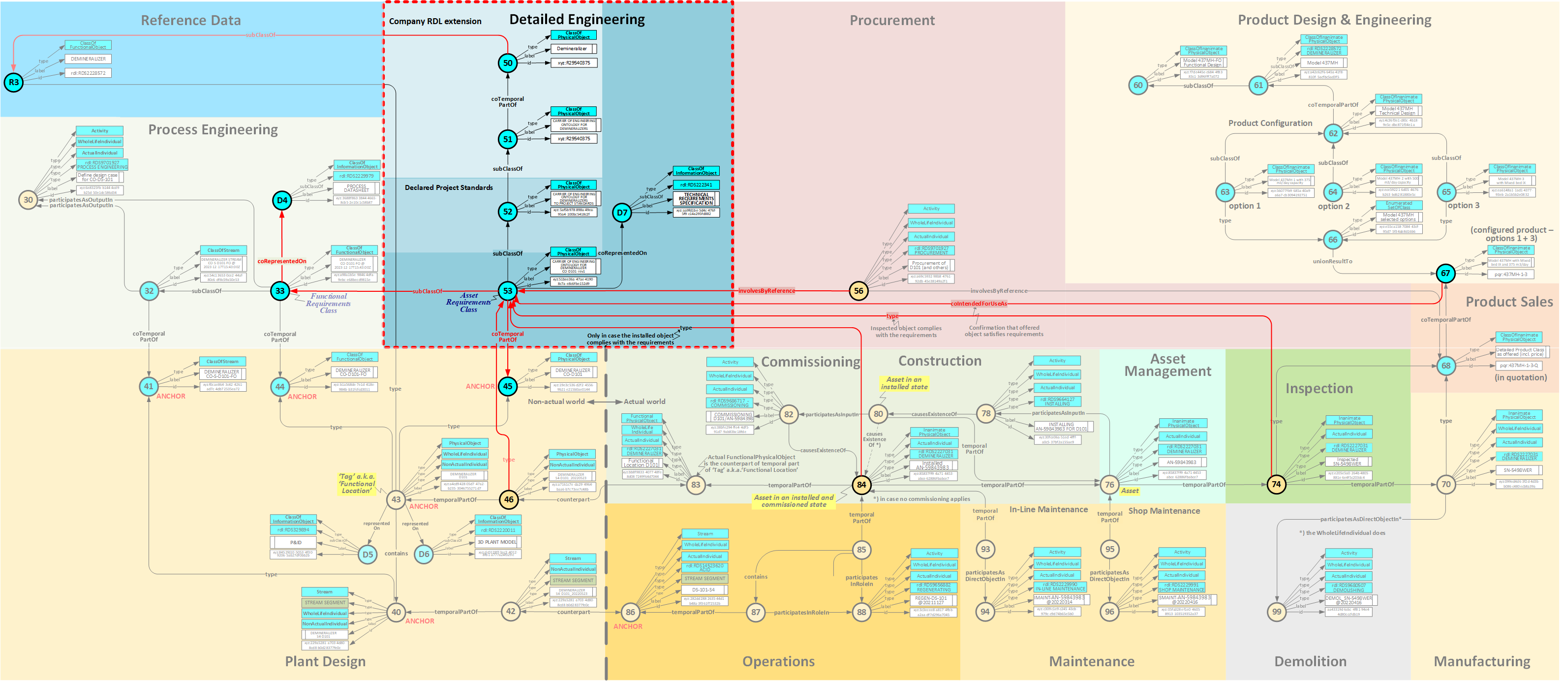
Similar to the definition of information sets in Process Design, here infosets for the hardware requirements are defined in a local RDL extension [52]
The functional information, defined in Process Engineering, is inherited since the Asset Requirements Class [53] is a specialization of the Functional Requirements Class [33]. The technical requirements are being added. The full definition of the Asset Requirements Class are recorded in the Technical Specification [D7]
A warning is due: It is not always so that the FunctionalObject and the PhysicalObject are of the same composition. You can functionally require things that are physically less simple. An example: A typical control valve has 2% leakage when closed, this means at best a rangeability of 50:1. In case a larger rangeability is required, then a combination of two control valves in parallel with split range control must be engineered: One larger valve with an equal percentage trim and a soft seat and a smaller valve with a linear trim. The PFD, if propertly defined and representing Functional Objects, just calls for a control valve with 62:1 rangeabilty.
The engineering history remains accessible by means of the construct using a ClassOfTemporalWholePart relationship between the 'anchor' ClassOfPhysicalObject [45] and its version [53]. The declaration of a new temporal part of [53] coincides with the issue of a new revision of the Technical Specification [D7].
Interfaces with other Life-cycle Activities
Detailed Engineering has a number of links with other life-cycle activities:
Code listing for this life-cycle activity
Click here
Product Configuration
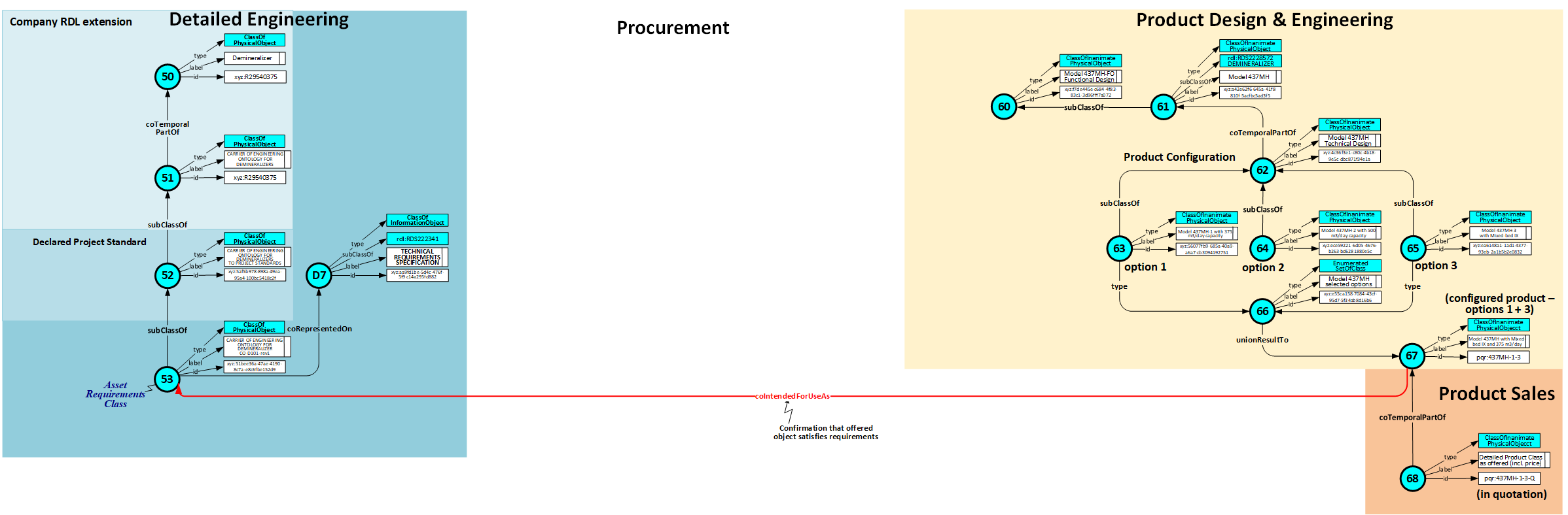
Product Configuration is done by engineers when making a selection of options of a reference ontology or a supplier catalog.
It is also done by a supplier when preparing a quotation. It follows this typical model that has been discussed in the topic 'Catalog options'
To the base model [62] the required options [63] and [65] have been added to arrive at a fully detailed technical model [66].
A coTemporalPartOf [67] is the ClassOfPhysicalObject [68], that includes commercial and logistical information, as recorded in a Quotation.
Code listing for this life-cycle activity
Click here
Product Sales & Procurement
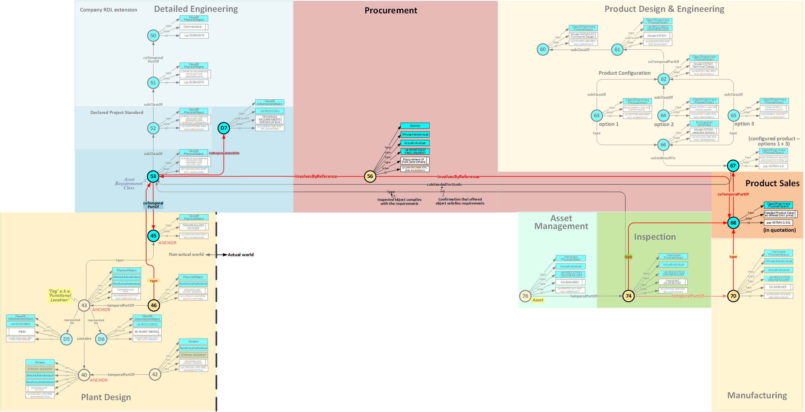
The ClassOfPhysicalObject [68], that has been offered by a supplier. It is a coTemporalPartOf the configuration result [67] . It adds price information and other commercial and logistical information.
The ClassOfPhysicalObject [68] is 'involved by reference' in Procurement Activity [56] together with the Asset Requirements Class [53] ; the defining specification [D7] is a part of an RFQ (Request For Quotation) and PO (Purchase Order).
The PhysicalObject [70] , that is manufactured, is classified with the ClassOfPhysicalObject [68] that has been offered and accepted.
Code listing for this life-cycle activity
Click here
Manufacturing & Inspection
Once the product [70] has been manufactured it shall comply with the quotation. This is put on record by classifying it with [68]
Then it is often been inspected. That inspection is done to PhysicalObject [74] that is a temporal part of the manufactured product [70]. It must comply with the quotation [68] with all included documentation of the manufacturer, and with the Technical Requirements Specification [D7] .
The fact that the product [74] is found in accordance with the Specification [D7] is recorded with the Classification relationship between [74] and [53].
Code listing for this life-cycle activity
Click here
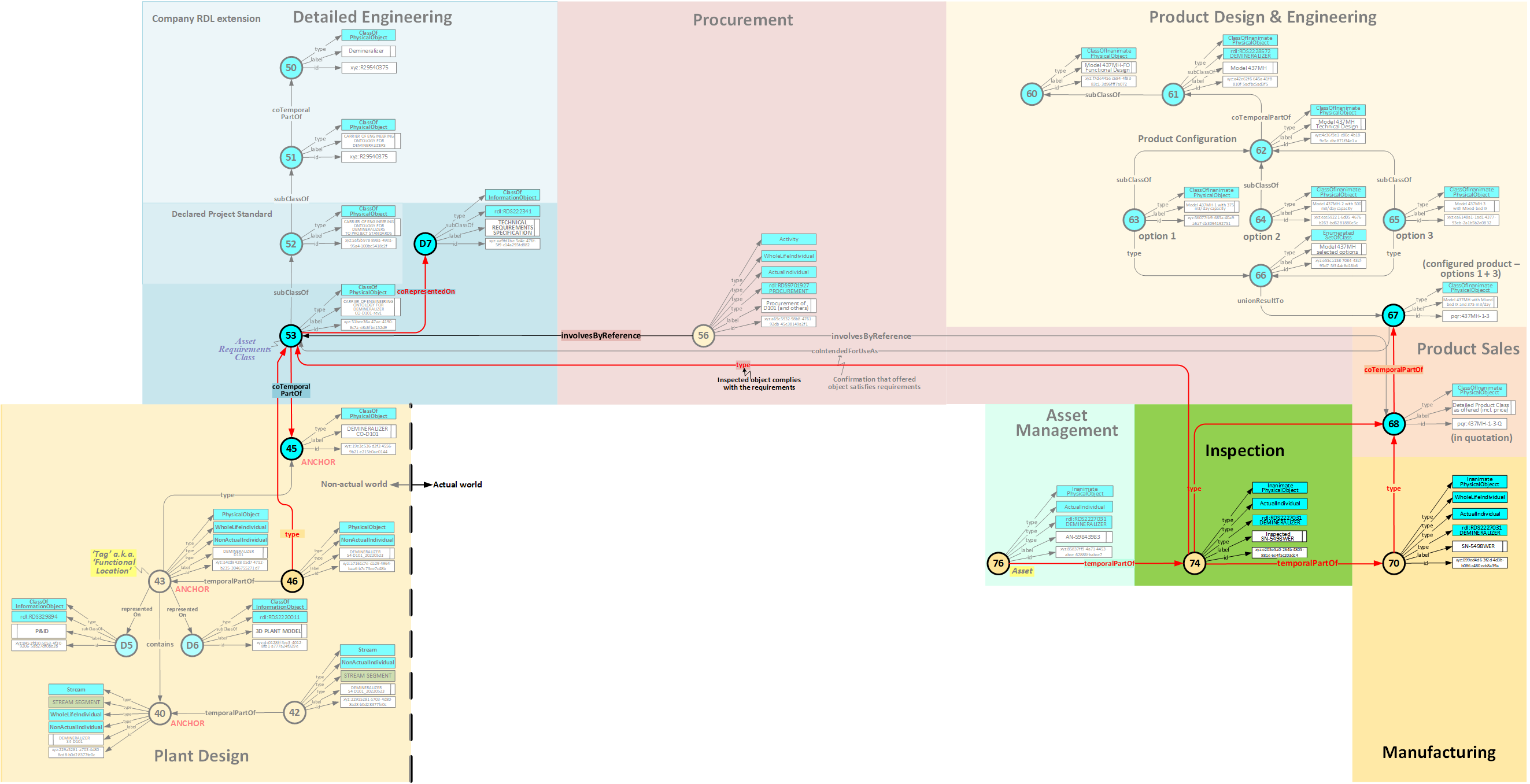
Asset Management
The inspected product [74] is shipped to the plant site.
Then, or later, the PhysicalObject [76], a temporal part of the inspected PhysicalObject [74], is registered in the plant owner's books and gets an Asset Number (where applicable).
That Asset [76] can be installed, resulting in [84], or maintained [95].
Code listing for this life-cycle activity
Click here
Construction & Commissioning
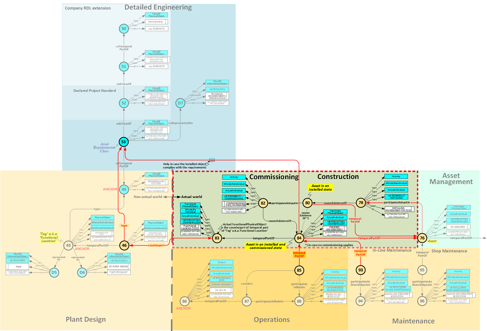
A temporal part of Asset [76] participates in installing Activity [78] that causes the Event that marked the beginning of another temporal part of Asset [76] : the Asset in installed state [80] .
Asset in installed state [80] may, when applicable, participate in commissioning Activity [82] that causes the Event that marked the beginning of a temporal part of Asset [76] : the Asset in installed and commisioned state [84] .
The latter has the following relationships:
Code listing for this life-cycle activity
Click here
Operations
A temporal part [85] of the Installed Asset [84] participates in Activity [88 ] as does temporal part [87] of Stream [86];
A temporal part [85] of the Installed Asset [84] contains temporal part [87] of Stream [86] ;
Stream [87] is, for a given process case, the counterpart of the Process Design Stream [17]
Asset [85] is, for a given process case, the counterpart of the Process Design FunctionalObject [27].
This gives access to the Process Design data (iff having access rights).
Code listing for this life-cycle activity
Click here
Maintenance
There are two types of maintenance:
Code listing for this life-cycle activity
Click here
Performance Analysis
In case:
Code listing for this life-cycle activity
Click here
Demolition
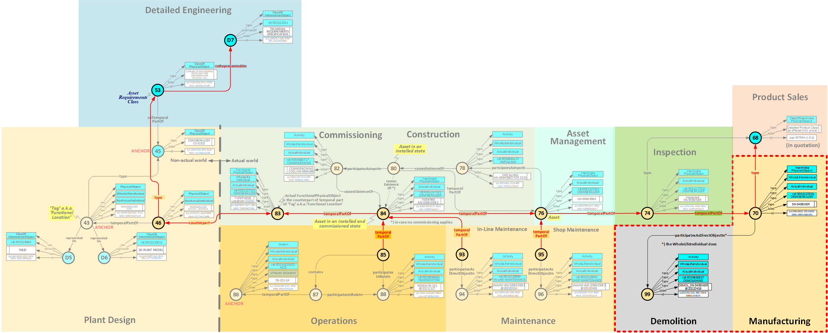
Everything comes to an end, so does a plant or a plant item. Demolition activity [99] has the WholeLifeIndividual [70] as a participant. This does not mean that we throw away that item from the data base, we just add the triple:
ex:UUID-of-[70] meta:valDeprecationDate "yyyy-mm-ddThh:mm:ssZ"^^xsd:dateTime .
to the declaration (in fact ) of that item and all its declared temporal parts and temporal parts thereof, AND all Template instances in which oanyone of them plays a role !!!. That can be found fairly easily with SPARQL queries.
It is upto the software supplier to let that be known to any user or any application that is interested in that deprecated plant item or a declared temporal part thereof, directly or when referred to in a template signature. Insert an existence check in any SPARQL query (that is necessary anyway to avoid multiple declarations).
Code listing for this life-cycle activity
Click here